Step One: Upload GIS data to the “My Content” section in ArcGIS Online
You’ll need to have your GIS data uploaded because we will be using the Autodesk Connector for ArcGIS. This tool links to your ArcGIS Online account and will insert your GIS data as Civil 3D objects. In our case, pipe networks and structures.
Step Two: Open a Civil 3D session after data is uploaded
- Make sure you set up the coordinate system properly and that it matches the data you’ll be importing.
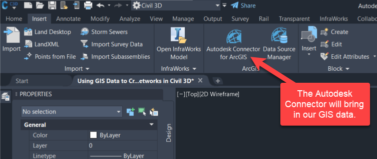
- Under the insert tab, select the Autodesk Connector for ArcGIS tool. This will display a selection window with a map.
- Zoom into the area on the map that will encompass your data. Once you select the area you’re working in, you will be prompted to select from the ArcGIS Online library of data. (Public, My Content, My Groups, Organization)
- Navigate and select the pipe and structure data you plan to import and identify them as such.
- Click Add
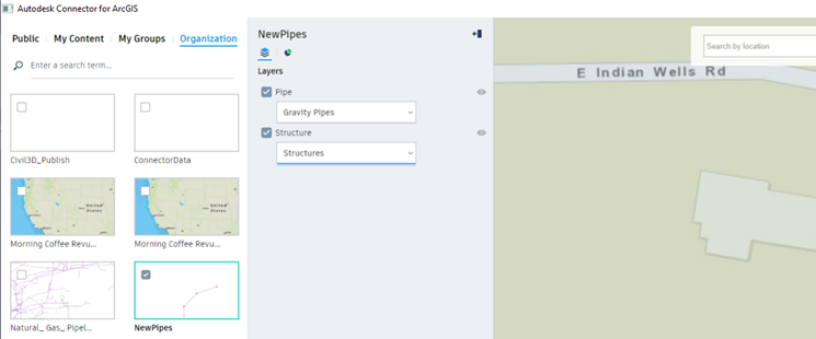
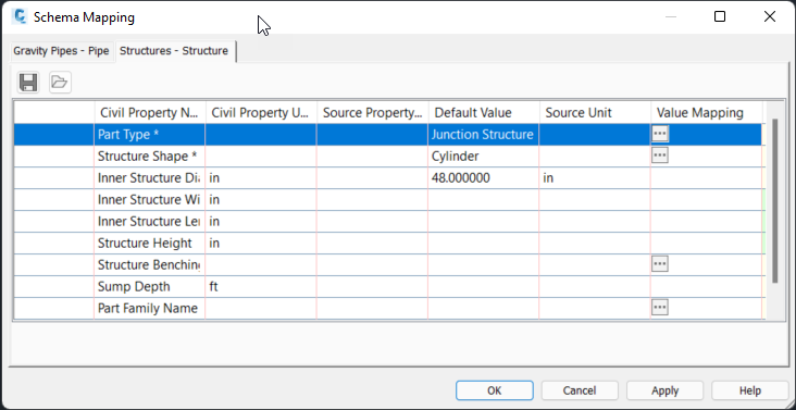
You will be prompted to map the schema types within the data for CAD to translate. Update or accept the default values according to your needs.
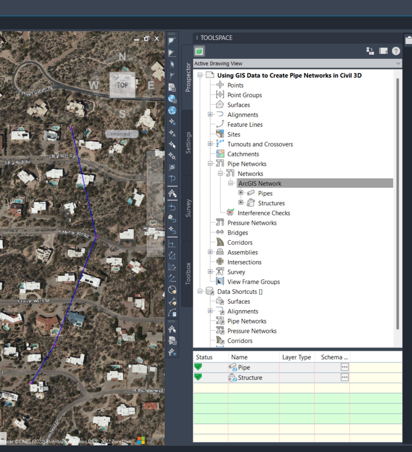
Your data will appear under Pipe Networks > ArcGIS Network > Pipes & Structures.
Step Three: Use CTC tools to modify the network
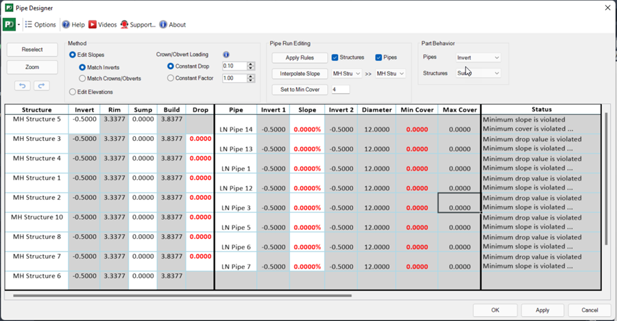
In the CIM Project Suite toolset, select Pipe Designer.
- Select the ArcGIS Pipe Network from the first manhole to your last.
- This will encompass the whole network between those manholes.
- Now that Pipe Designer is open, you can start editing your data.
